Introduction

Fuzzy Logic Controllers (FLC) are a good way to define a heuristic based control algorithm that is simple and robust across a wide range of operation. Compared to traditional controllers like that of PID controllers which cannot handle non linear responses properly, FLC have no issues with non linearity. These are also easier to make and tune and require some basic computation in order to set the control rules.

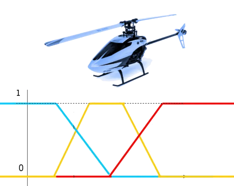
Compared to traditional boolean logic which has either true or false values, fuzzy logic operates on multiple ranges of descriptive qualities to model a system. These are modeled as a distribution functions. The values in these might vary based on different parameters in the system.

Goals

Rotary aerial vehicles have their motions coupled as these systems are underactuated.

The goal of this project was to develop a basic fuzzy logic controller to control the motion of a UAV helicopter based on its main rotor and tail rotor inputs.

Work Done

A UAV helicopter has 6 degrees of freedom: 3 translational and 3 rotational ones. To simplify the problem, it was decided to make a controller that would be able to at least control the throttle (up-down) and yaw motion of the UAV.

The equations of dynamics that govern throttle can be given by the lift generated by the main rotor propellers countering the weight of the UAV. This rotational torque causes the UAV to yaw in one direction. In order to stabilize this generated torque, the tail rotor must provide a torque in the opposite direction at all times. Otherwise the helicopter will keep on rotating in one yaw direction.

The fuzzy logic controller (FLC) requires positional and angular velocity member function inputs to base an output upon. Based on the control logic it will output a PWM torque value. The controller in itself has the logic encoded in a table of prompts which map each input type to an output type. This table can be edited based on how much control we want to exercise over the system and can also include more parameters.

Then we must define in what region must each of these member functions operate. This is where the fuzzy part comes in. This explicitly explains to the model that for a given value of a parameter, which output to select for the membership function. The controller to be used is a Mamdani type controller.

The membership functions for position, velocity look like as shown in the figure for the flight controller. They have regions from Negative high to Positive high for the position and similarly Negative fast to Positive fast for the velocity. Each of these is mapped to a corresponding PWM torque value the controller must choose. The controller thus outputs a variable PWM membership function which is shown below.

Results

To test this controller design, a simulation of the main and tail rotor of the UAV helicopter was made in MATLAB Simulink. Appropriate values were chosen for the constants based on the dynamic model assumed earlier. The parameters needed some fine tuning due to the simplification assumptions made in the model. After integrating the FLC into the simulation, the simulation seemed to perform decently.

When given a target input position, the controller quickly adjusts the positional delta and gives a PWM output to move in the given direction. It stabilizes itself in 5 seconds. However, there is slight overshoot initially which causes it to oscillate about the position for a few times before finally converging to a steady state behaviour.

Simulink Model

Contact me!

๐Ÿ“ž(404) 388-3944    ๐Ÿ“Atlanta, GA, 30309   ๐Ÿ“งbhushan.pawaskar@hotmail.com

ยฉ Copyright 2023 Bhushan Pawaskar - All Rights Reserved